
Hello!
There was a task to develop a compact antenna with a boom length of no more than 2 meters, in the range of 70cm to work through the repeater spacing in frequency -7.6 MHz.
Terms on the line between reporter and repeater 70km and overlap on the terrain.
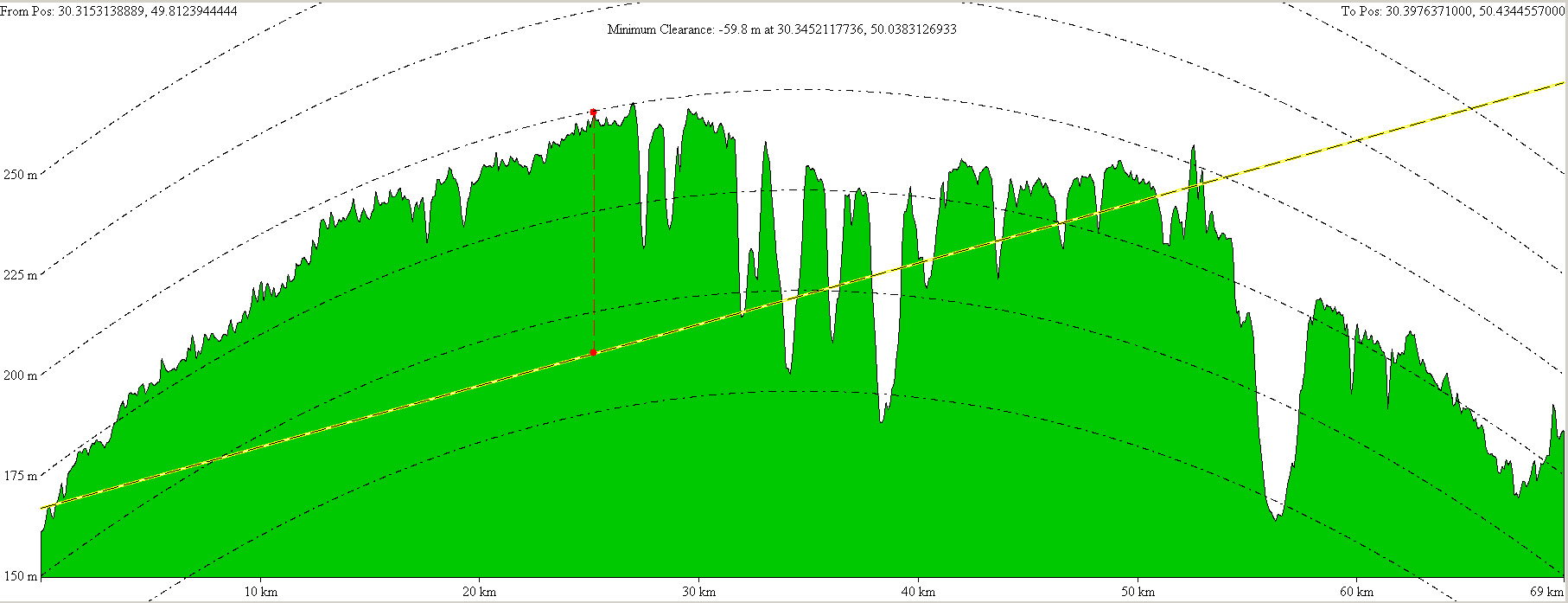
Start Height: 166.778 m
End Height: 272.71 m
Straight-Line Distance: 69.4427 km
3D Distance on Surface: 69.4948 km
Vertical Difference (Start to Finish): 105.9 m
Minimum Elevation on Path: 117.913 m
Maximum Elevation on Path: 204.966 m
Azimuth: 4° 49′ 53.7″
Slope/Tilt: 0.09°
Min LOS Clearance: -59.846 m
Min LOS Clearance Location: 30.3452117736, 50.0383126933
Baseline Elev at Min LOS Clearance Location: 205.25 m
Losses at 170 dB line
In order to communicate the necessary data: repeater antenna gain, loss feedline loss duplexer receiving path, as well as the level of detection transponder receiver.
The last we do not know, we take the optimal conditions for repeater: 6dBi antenna gain, loss of AFU and duplexer 1,5dB, reference level receive 9 points -93dBm.
To solve this problem we can go on increasing the transmitter power at low gain antenna or increase the antenna gain.
Since TK was given a maximum length of 2 meters boom, then put in the wave structure of more than 10 elements is not possible and gain limited 12dBd.
According to the calculations we needed at the level of the supplied antenna to + 46dBm (39.81Wt) strengthening of the latter is necessary to 19dBi.
Boom of antenna square pipe 20×20 mm (25×25). Reflector and directors AD31 alloy (32) 8mm mounted on insulators made of plexiglass, the distance between the surfaces of the boom and elements of 10mm, a minimum of 5 mm.
Vibrator diameter of 10mm copper pipe in a project to reduce losses. The gap between the arms of the dipole 10mm (air). Elements of the vibrator must be supplied with tap up to 7mm.
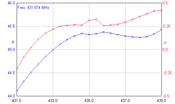
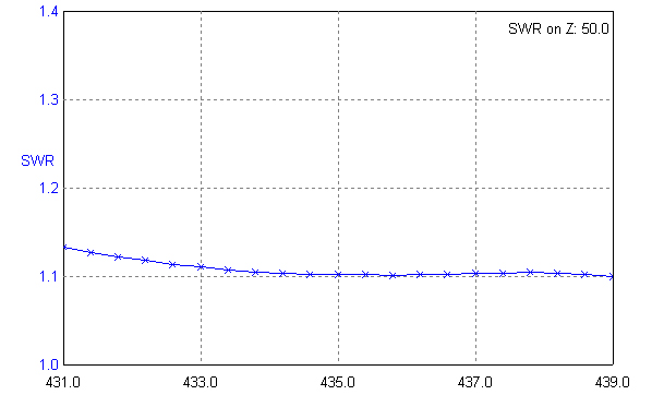
The performance characteristics of the antenna:
Element Position Length element
Reflector 0mm 339mm
Vibrator 158mm 306mm
Director1 232mm 300,5mm
Director2 407mm 293,5mm
Director3 631mm 280mm
Director4 936mm 277,5mm
Director5 1191mm 280,5mm
Director6 1463mm 274,5mm
Director7 1740mm 280mm
Director8 1952mm 272mm
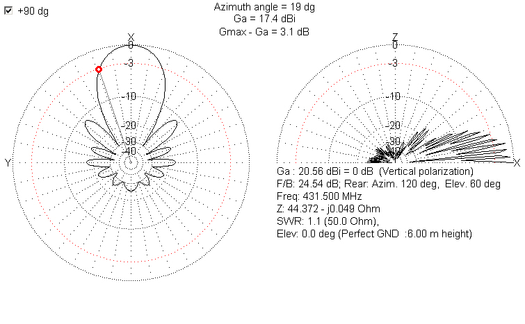
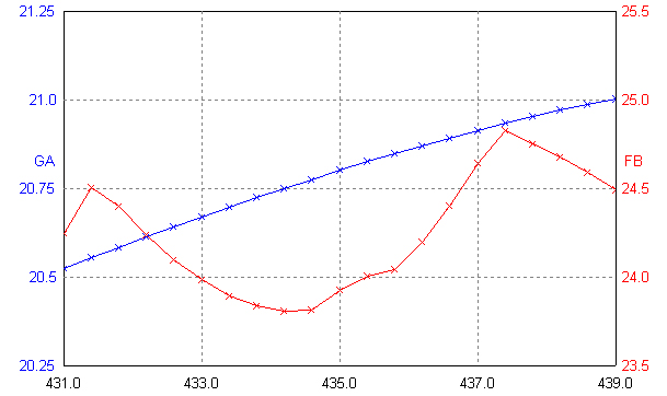
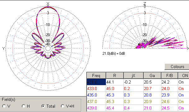
Transmission and reception of the problem is solved by the maximum possible amplification ratio of front / rear, and the maximum gain in the transmission and reception frequency bands.
Recent Comments